My First Drawing
After creating a part in chapter My First Part and assemble the part in an assembly in chapter My First Assembly we will now create a 2D drawing in dxf and svg file format.
Drawings are very helpful for production. We can make different views of a part or assembly and add some dimensions to get an idea about the size of the part or assembly. In this tutorial we will use our flange part from the chapter My First Part
1. Create some different views#
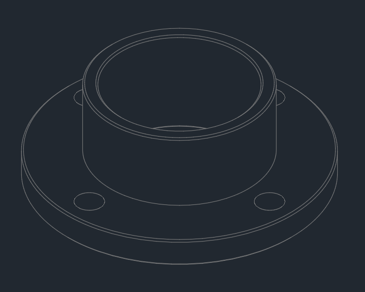
With the history api we are able to create different views, e.g. top, bottom, front, right, ... To start with a simple view, let's create the iso view of the flange part. We will use more or less the same code we used for creating the part and add the following snippets to this code.
You will be prompted to save the dxf file somewhere on your local system. After saving, open it with a common dxf viewer you will find in the internet.
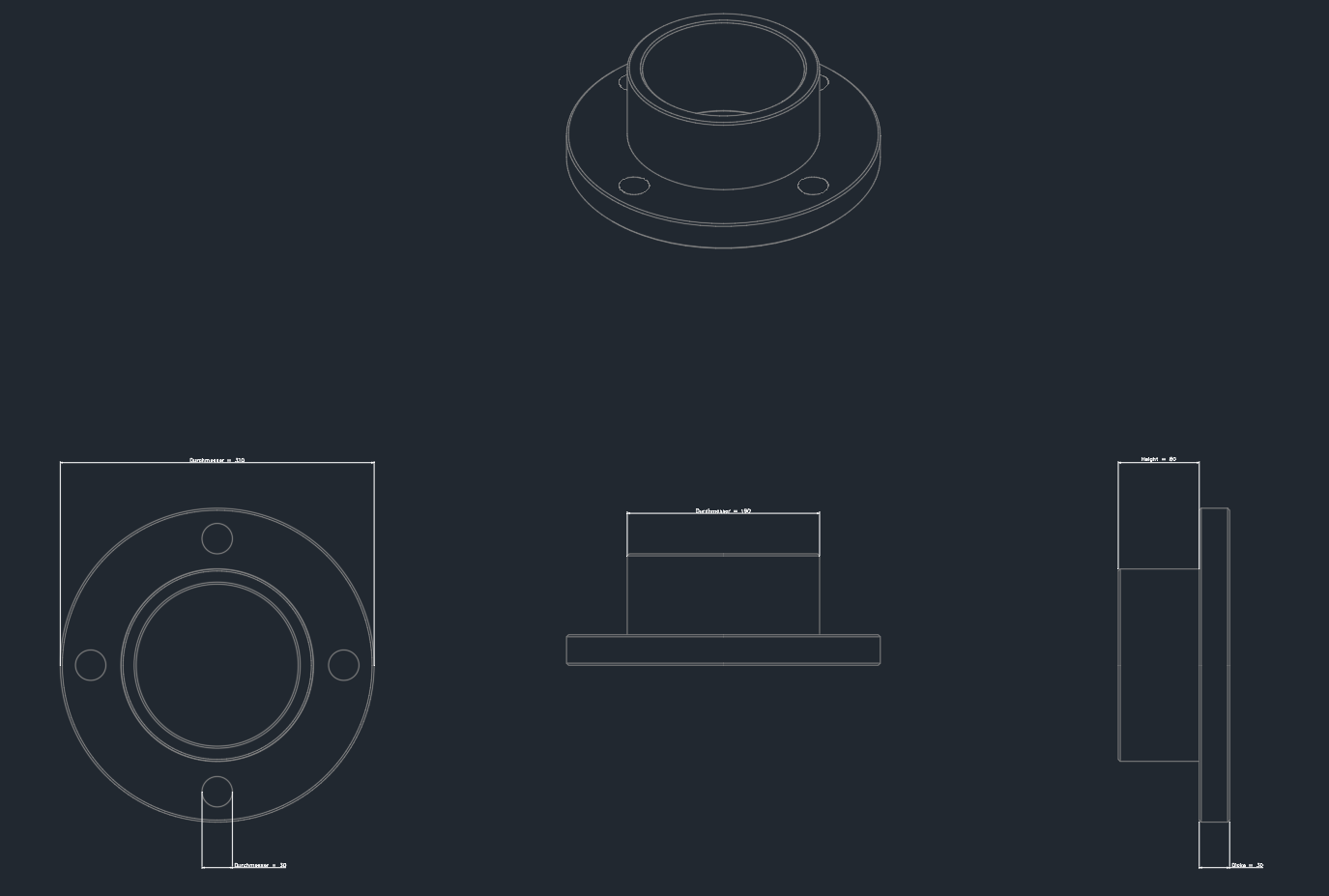
This will be the result of the dxf export.
In the end we will have a dxf file which containst a top view, right view, right 90° view and the iso view. So we need to add the other views also to the code.
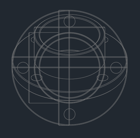
As you can see all the views are at the same positon, which doesn't make much sense. We need to place the views. Insert the following line of code after creating the views.
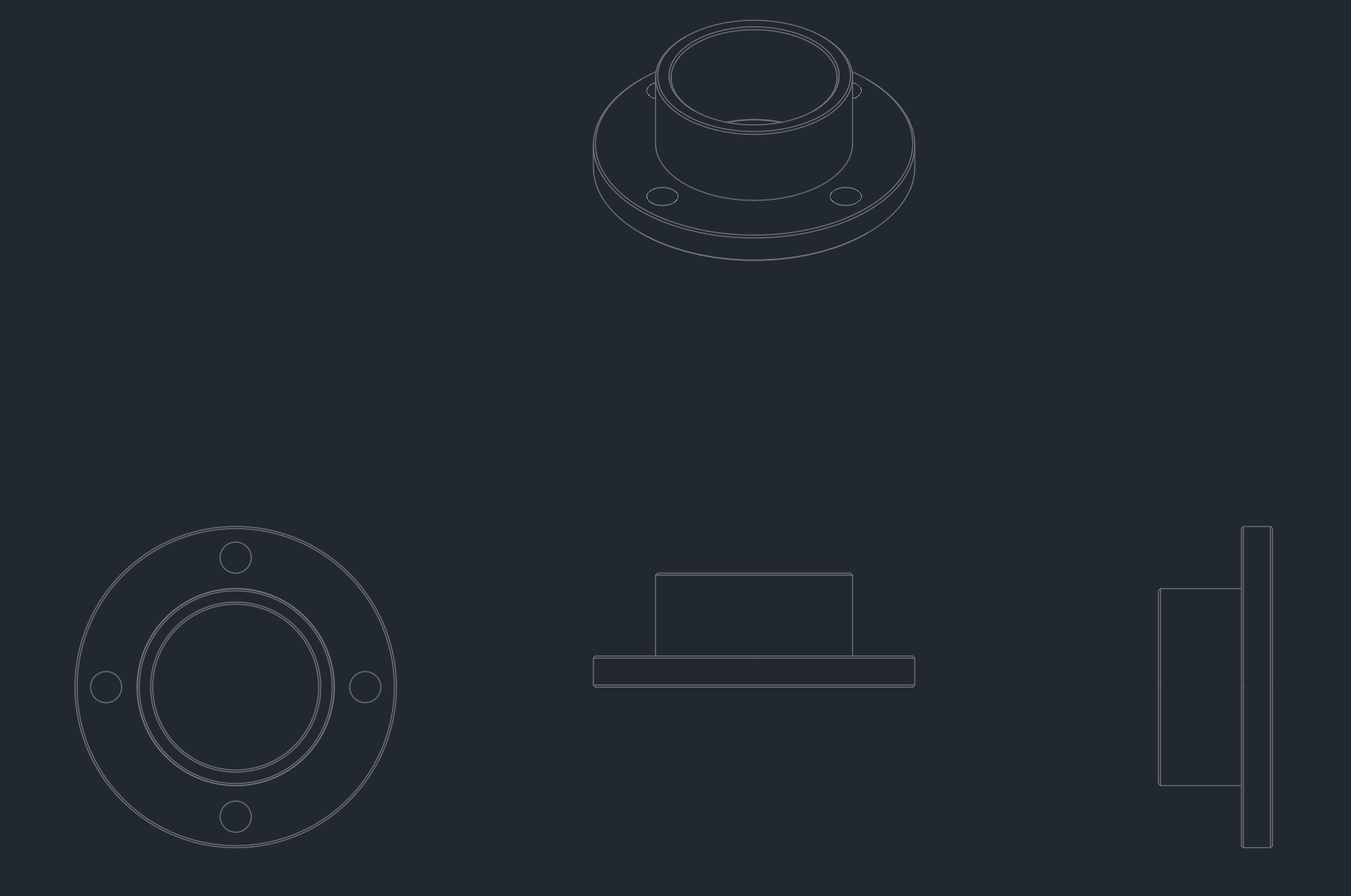
Now we have a clean drawing. Next step will be to add dimensions to the view. We will do this in the next chapter.
2. Add dimensions to the views#
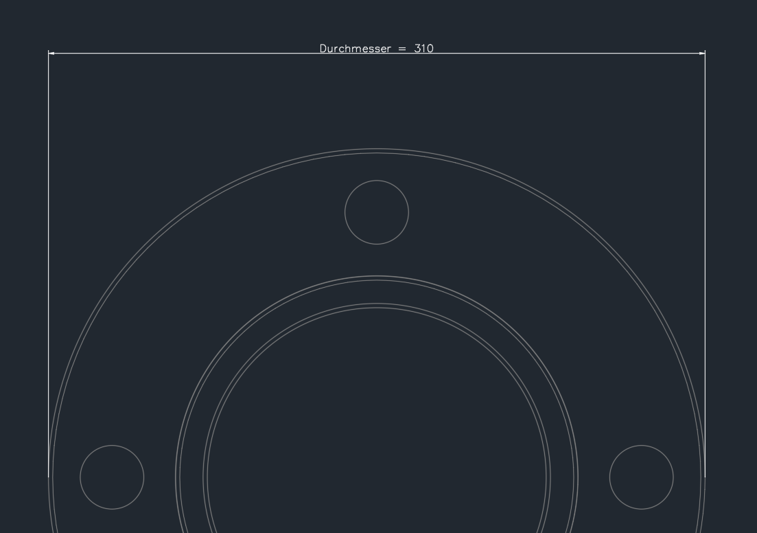
We will start with a dimension in the top view. In the flange part it could make sense to add a dimension for the diameter. What we need to do is to define the following parameters:
- type of dimension
- label
- start position
- end position
- text position
- text angle
- orientation of the dimension
- view where the dimension will be visible
Some more parameters are optional and not necessary at the moment. Copy the following code snippet into your template.
To make sure that the dimension will be added to the view, add the following snippet just before the line of code where the views are created. All additional dimensions which we create later, will automatically added to the view.
As you will see in the dxf file, the flange has become a diameter dimension in its top view.
Now we add another dimension in the top view but also in the other ones. The following snippet creates a dimension for one of the holes. We also use it to describe the diameter.
In the right view we add a dimension for the diameter of the upper cylinder
In the righ 90° view, which is actually the right view but rotated by 90°, we add two dimensions. One dimension for the height of the upper cylinder and one for the thickness of the base cylinder
3. Export the views as dxf or svg file#
Exporting the views as dxf file is quite simple. We've already seen in chapter 1 how to do that with dxf. Actually there is one line of code needed:
You will get the stream as return value and you can do whatever you want with it. In chapter 1 we prompt a window to let the user decide where to save it. It's the same with svg. Just one line of code is needed.