Sketches
In the headless environment where we use program code to build our models, it's not practicable to draw sketches with different curves and constraints. Without a GUI it's probably not possible to create sketches in a classic workflow, like we do in buerligons. As already explained in Sketches we use sketches to build complex models. In the solid API we use Shapes and Polylines to draw simplified sketches, which we can extrude or revolve later. The concept in the history API is about to load and copy sketches from other parts, which have been created with buerligons. There are actually two ways using sketches. We can load a sketch and extrude or revolve the whole sketch. The other way is only to use regions of the sketch called "Sketch Regions". A sketch region can be a part of an complex sketch. These regions can be defined within the sketch plugin of buerligons.
1. Using whole sketches#
If you want to create a model which needs five different sketches, you can draw all sketches in buerligons and give each sketch an identifying name. This name can be used to load the sketch into the model which you are coding right now.
The easiest way to use a sketch is to simply place it on a workplane. We can create the workplane with createWorkPlane(...). After that we can load the sketch and place it on the workplane with loadSketch(...). To see the sketch we extrude it with extrusion(...).
It's even possible to place sketches on other solids. For example if we want to place it on box, we first have to create our workplane of the top face of the box, by selecting this face. Later we can choose this workplane like we did before. Let's do it by code:
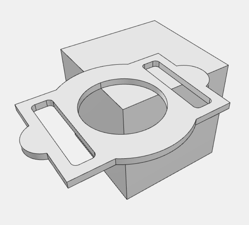
As you can see, the center of the sketch has been set to the upper corner in the front. This is a default position and has been calculated due to the drawings center and the face of the workplane. To place the sketch in more detail we can use placeSketch(...). See the api to get more information about positioning. If we only want to have the center of the sketch in the center of the top face it's enough to define the origin position. See the following code snippet:
💡 Tip: To make positioning of sketches as easy as possible, try to draw the sketch, so that origin {0,0,0} is in the center of the sketch
It's also possible to rotate the sketch. In that case we also need to define an axis beside the origin. For example if we want to rotate about 90° ween need to define a workaxis which has y-axis direction. See following code:
2. Using sketch regions#
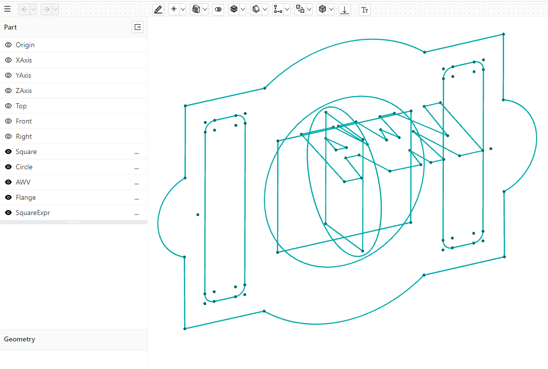
Sketch regions are quite helpful to split up a complex sketch into smaller parts and use them individually for further operations like a revolve or an extrusion. We don't have to draw them in separate sketches. Often it's easier to draw the regions within the same sketch, because we can use sketch lines from other parts of the sketch which they rely on. The following picture shows a sketch with different regions. One of the regions is highlighted (orange lines).
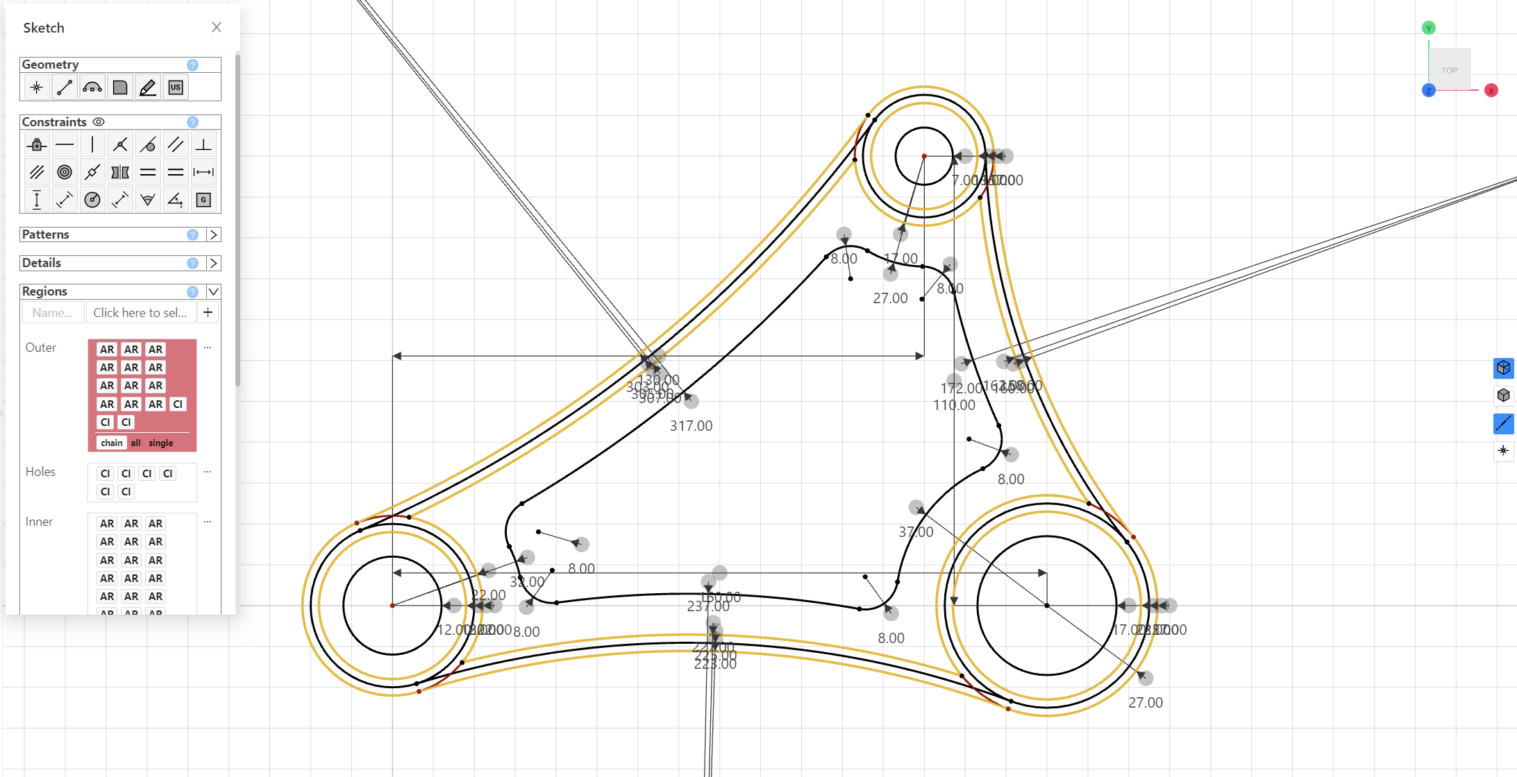
You can see in the sketch plugin on the left side in the picture above, that there are two more regions defined. The currently selected region is called "Outer", but there are two others called "Holes" and "Inner". In this example, which also can be found on buerli-examples, we exactly make use of these different regions. Because we want to extrude those regions differently.
Like we did in the example with whole sketches, we're going to create a part, a workplane in that plane and load the sketch on to that workplane. See the following code snippet:
We have now loaded the sketch into the part which contains the regions described above. We can simply get the regions by their names. Then we can just extrude the regions with the height we want.
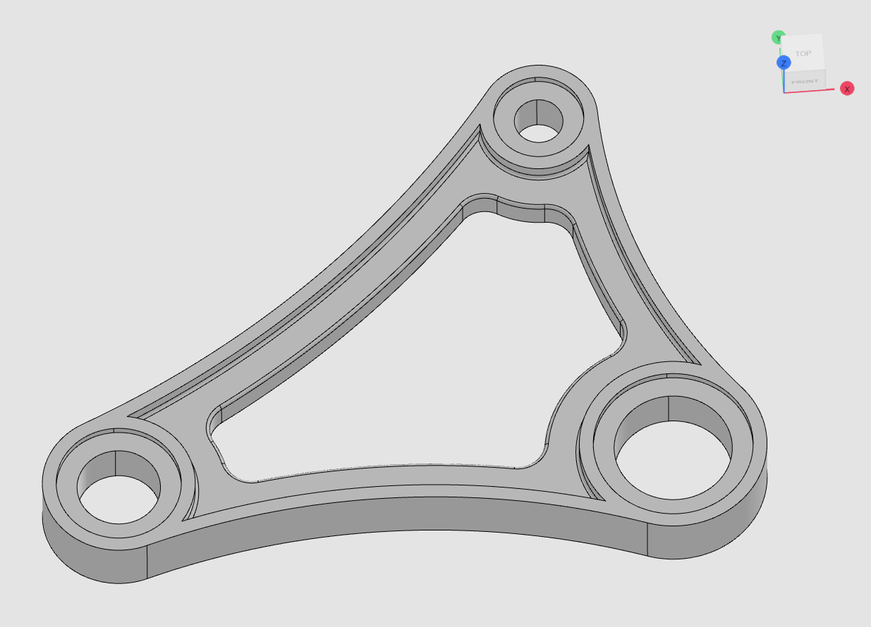
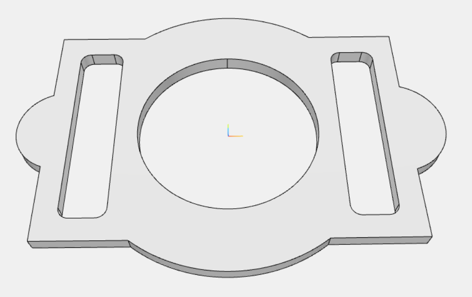
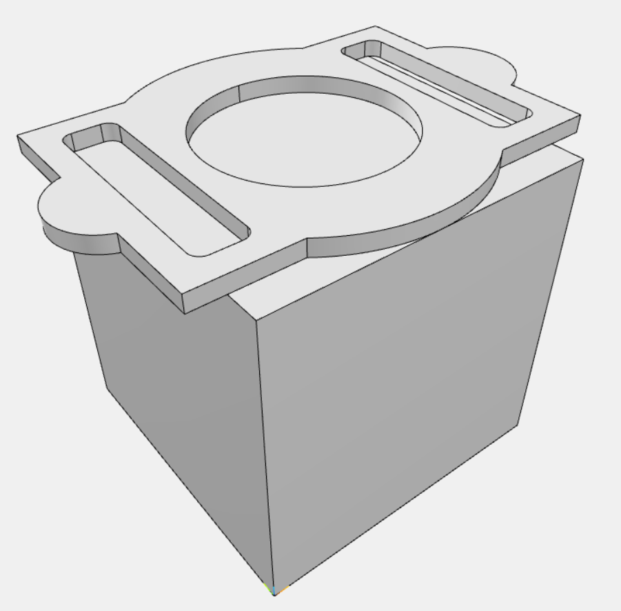
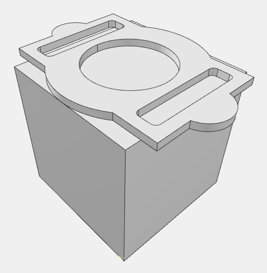
After these operations it will look like in the picture below. If you take a closer look, you can see that there are also some fillets between outer an inner extrusion. To create those fillets we need to do another operation, which will not be discussed here. Just see the example in our buerli-examples application, there you can see how to create them as well.